Technical Article
Published 08/2023
Electricity Distribution using Two Wire Single Phase
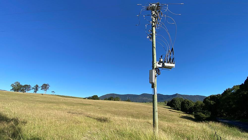
There are multiple ways to design the electricity network for distributing power at 11 to 38 kV. From a standards point of view, networks are either designed to the IEEE North American standard, relying on a four-wire system with phase-to-ground transformer connections, or to the European style IEC network relying mostly on larger 3 phase transformers.
Under the European style of electricity distribution, there are three methods of network design. In descending order of power transfer capability, these are:
- Three Wire Three Phase
- Two Wire Single Phase
- Single Wire Earth Return
The vast majority of distribution uses the three wire three phase method. The remaining two methods of electricity distribution are generally applied to lightly loaded rural feeders, where the load does not justify the cost of running the three-phase network out to remote locations.
Single wire earth return distribution uses only one line, where the circuit return path is through an earth connection at the far end of the line. This is the cheapest method of power distribution but has issues for safety. Failing earths break the circuit, and worse yet, failing earths at the far end of the line can introduce dangerous step potentials.
The safer alternative is to rely on two wire single phase, where the return path of current does not rely on the earth connection in proximity to the public.
In this article, we review the application of two wire single phase distribution, and how to protect and control these feeders with auto-reclosing circuit breakers.
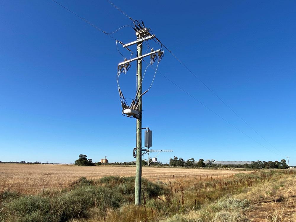
Two Wire Single Phase Distribution
Two wire distribution lines are connected to the three phase European style backbone feeder. They are usually connected phase to phase, as shown in figure 1.
Phase to Phase Connected Single Phase Spur
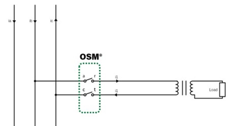
In this connection topology, it is equivalent to taking a three-phase spur, but omitting one of the lines.
The voltage between the two lines in the single-phase arrangement is the phase-to-phase voltage of the backbone. That is, if the feeder backbone is 22 kV phase to phase, then the two-wire single phase voltage is also 22 kV phase to phase, with voltages 120 degrees apart.
The current however is 180 degrees apart. This introduces the limitation of single-phase distribution from a three-phase backbone – current unbalance seen on the main line.
The load at the end of the line is connected through a phase-to-phase transformer.
Protecting Two Wire Single Phase – Connecting an OSM Recloser
In figure one, the two circuit breaker icons are representative of a NOJA Power OSM Recloser two phase device.
Each phase has a current transformer, and voltage sensors on either side of the interrupter.
NOJA Power OSM Recloser terminals are designated ABC and RST. In the two-pole connection topology, only phases AR and CT are connected, with the B to S phase either missing (when using a two-pole device), or left disconnected when using a three phase device.
Using a three-phase device is common practice when future network augmentation would suggest conversion to three phase is likely.
Fault Scenarios for a Two Wire Single Phase line.
Protection for two wire single phase lines is designed to trip on line-to-line and line-to-ground faults.
Line to Line Faults
When a line-to-line fault occurs downstream of the protective device, a short circuit is introduced. This will greatly increase the current flowing through the device, but the angle remains 180 degrees apart.
Conventional phase overcurrent protection is used to protect assets in this situation. The setting selected is above the peak line load. The NOJA Power OSM Recloser can also use Inrush Restraint at this point to handle line reenergisation without spurious tripping.
Earth Faults
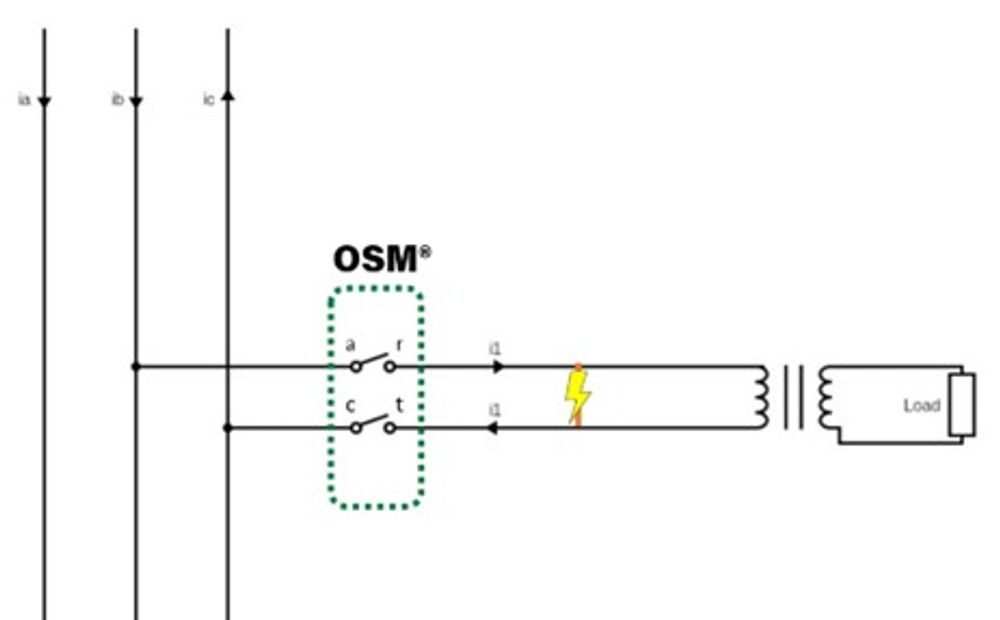
Earth faults occur when there is a failure of insulation of the system, leading to a conductor coming into contact with the earth. This could be through a tree leaning on the wire, or animals bridging across insulators phase to ground. Figure 3 shows an example of this case.
When an earth fault occurs, a connection to earth introduces two paths for current. One is back through the CT phase of the recloser, and the other flows through the far end of the spur, through the transformer windings, and back through the AR phase of the recloser.
The current is likely to be different on the two phases. The phase closest to the fault, (phase CT in Figure 4), would see the higher current. The AR phase current path has more impedance, as the current needs to flow through the transformer at the end of the line.
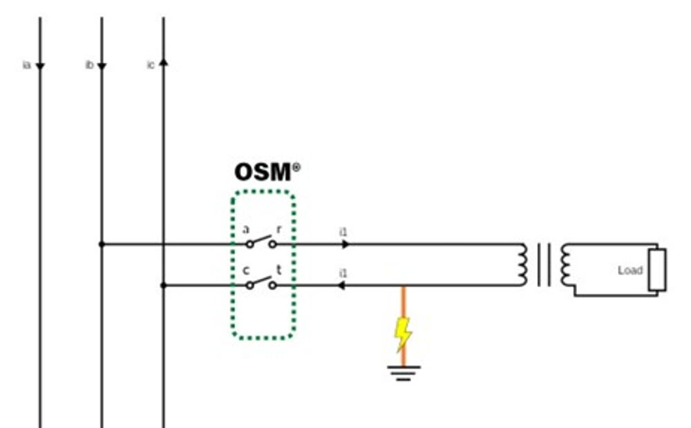
The closer the earth fault is to the recloser, the larger this disparity, and the larger the fault current seen by the closest terminal. The current magnitude depends on the fault impedance itself. While Overcurrent protection will often detect real-world faults, earth fault protection is the correct protection method to address this fault.
Since the addition of an earth path changes the phase angle relationships, a neutral current will appear.
Therefore, Earth fault protection is possible on two wire single phase networks. General settings examples that have been applied in the field are around 20 to 25 A of calculated neutral current. However, a feeder protection study would be necessary to calculate the correct settings.
The recloser itself can be backed up by main line earth fault protection.
Limitations and Considerations of Earth Fault Protection on Two Wire Single Phase lines
Two wire single phase lines are commonly seen on networks that also include Single Wire Earth Return networks. All SWER networks innately introduce standing neutral currents. As this neutral standing current increases, the sensitivity to earth faults reduces.
On networks that don’t have SWER, it is technically plausible to include Sensitive Earth Fault protection on two wire single phase. The standing neutral current may be sufficiently low that applying SEF would not introduce nuisance tripping.
Conclusion
“We manufacture our reclosers in 3 phase, 3 phase single triple, 2 phase and 1 phase configurations to meet all applications globally,” says NOJA Power Group Managing Director Neil O'Sullivan.
“ This is a great example of how our 2-pole device is used in a single phase 2 wire application providing both overcurrent and earth fault protection. ”
Two wire single phase is a valid distribution network topology. NOJA Power offers a two pole OSM Recloser build option for this scenario, and the key OSM Recloser protection features used are Overcurrent and Earth Fault Protection.
For more information, visit www.nojapower.com.au or contact your local NOJA Power Distributor.
Want to stay up to date with Electrical Distribution Technology?
Join our list for a free weekly technical bulletin, as we share our Global Electrical Engineering experience directly to your inbox.
Subscribe →