Technical Article
Updated 03/2025
Cogeneration and Sync-Check with Reclosers: An Application Overview

Distributed Energy supplies and varied sources of generation are becoming increasingly common in the modern electrical system. Integrating these new sources of supply into existing power grids create a number of challenges for Power Systems Engineers.
In this article, we explore the cogeneration functionality features available in the NOJA Power RC controller products to assist in these projects.
This functionality can be used for the following applications:
- Connection of incoming generators to the grid
- Re-establishment of a connection between two interconnected parts of the network
- Re-establishment of a connection between islanded systems
Cogeneration features in NOJA Power’s RC Recloser Controllers can be subdivided into three main categories:
- General functionality
- Sync-Check
- Auto-Synchroniser
“Almost all of our customers globally today are challenged with integrating renewal energy generation to the distribution grid,” says NOJA Power Group Managing Director Neil O’Sullivan.
“Both IEC and IEEE Standards are emerging and evolving to help define best practise. We have developed the functionality required by these Standards and our products have now been approved by many of our electricity utility customers to be used as the connection point between large scale distributed energy generation and their distribution networks.”
Sync-Check Feature Overview
In consulting the standards, the ANSI 25 Synchronism code states:
“A synchronizing device shall produce an output that causes closure at zero-phase angle difference between two circuits... A synchronism-check relay permits the paralleling of two circuits that are within prescribed (usually wider) limits of voltage magnitude, phase angle, and frequency.” -Standard IEEE C37.2-2008
Synchronisation is used to ensure that two live networks are only connected at an Open switching device when the two independent sources are within pre-configured acceptable limits. Essentially, we are verifying that the voltage, phase angle and frequency are all sufficiently similar across the closing point to mitigate the risk of connecting unmatched networks.
Where should Sync-Check be used?
Synchronisation is important for a number of different applications. The key use is when you are connecting two separate live lines, and want to make sure they are synchronised before connecting them.
By synchronised we mean, voltage magnitude, phase angle and frequency are all within allowable limits.
Other applications include the connection of incoming generators to the network, the re-establishment of a connection between two interconnected parts of the network, and the re-establishment of the connection between islanded systems.
For example, a small customer can run as an islanded network for a while, then make sure it is safe to reconnect to the grid before the two lines are joined.
Understanding Sync-Check Working Limits
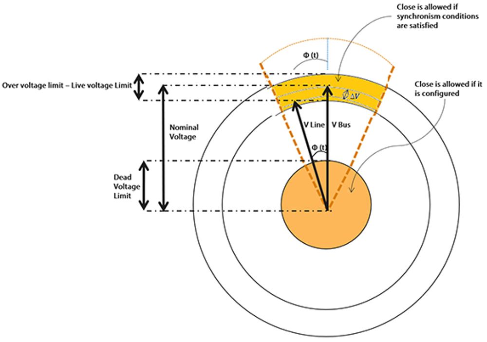
The following diagram illustrates the various limits of power system parameters applied in Sync-check. Understanding these is key to understanding sync-check.

The voltage on the line side of the recloser is given with the vector V Line, and the voltage on the bus side of the recloser is given with the vector V Bus.
The orange sections are the regions that the voltage vectors can be in and still allow a close. If either voltage vector is outside these regions, the close will be blocked.
For sync-check, consider the three factors of voltage, phase angle and frequency separately.
Voltage:
The voltage vectors must be above the live voltage limit (minimum voltage for the line to be considered safely live) but below the over voltage limit (maximum voltage for the line to be considered safely live).
If either voltage is outside of this limit or if the difference in the two voltage vectors exceed the specified voltage difference (delta v) the close will be blocked. The only exception to this rule has to do with dead voltage conditions.
Optionally the OSM can be configured to close if the bus side, line side or both sides are below the dead voltage limit. In this case, only the voltage magnitudes and not the phase angles or frequencies are considered when determining whether a close would be allowed.
Phase Angle and Frequency:
In addition to the voltage magnitude conditions, the auto-synchroniser and sync-check functions will check the phase difference and slip frequency between the two voltage vectors.
Referring to our figure, this is the “width”, left to right, of the orange zone in which a close would be allowed.
Auto-Synchroniser: ANSI 25 A
Taking our Sync-Check functionality a step further, we can automate a recloser device to only close when the synchronisation criteria are met.
When enabled, if a close command is issued to the NOJA Power RC Controller, it will hold the close command until all sync-check criteria are met. This holding period is configurable, and if it expires, the close command is discarded.
Want to stay up to date with Electrical Distribution Technology?
Join our list for a free weekly technical bulletin, as we share our Global Electrical Engineering experience directly to your inbox.
Subscribe →