Technical Article
Updated 03/2023
Demystifying Negative Phase Sequence Current Protection
The Key to Load Independent Current Protection

For modern distribution protection, Negative Phase Sequence (NPS) Protection is often relegated in favour of common elements such as Overcurrent (OC) or Earth Fault (EF), but NPS is a powerful function itself which adds selectivity and specificity to protection schemes with the capability to detect faults completely missed by common elements.
While it is more challenging to comprehend in comparison to its cousins in OC and EF, NPS is based on the same signals as conventional overcurrent. To demystify the functionality, we must look to symmetrical component Ttheory, explaining how the physical phase readings for current, voltage and phase angle are transformed into the Sequence domain, giving us metrics of Positive, Negative and Zero Sequence components.
For a high-level understanding of Symmetrical components, we can consider that the readings we take of the Phase values have no guaranteed relationship between each other. That is, if you know the current on Phase A, this does not mean that you can infer what current is present on Phase B or C.
Converting to symmetrical components, we take the readings from all three phases and transform them into a set of three elements (positive, negative and zero sequence), which by definition explain what each of the values are on all phases. For example, if you know the Positive Sequence current, you know what the total Positive sequence element is for all three phases.
By making this conversion, regardless of the imbalance in readings on Phase A, B and C, there is a specific combination of symmetrical components to describe that scenario that preserves the relationship between the phase readings on the main device. In matrix notation:

The three symmetrical elements are Positive Sequence (referenced with a 1 subscript), Negative Sequence (a 2 subscript) and Zero Sequence (a 0 subscript). These are vector quantities, where Positive Sequence assumes a perfectly balanced system with 120 degree phase rotation in the conventional direction. Negative sequence is the same, except rotating in the reverse direction, and finally Zero sequence which has no phase separation between its three components
Since we fundamentally know the relationship between sub-elements in a sequence component, (i.e. Vb,0 is always = Va,0, or Vb,1 is always 120° behind Va,1) we only need values for Va,0 Va,1 and Va,2 to represent any possible state of voltages for Va,b,c. The same can be said for the measured currents.
By doing this conversion, we create a relationship between all three phases, and allow us to infer different fault types based only on these 3 vectors.
What Each Element Represents
With the conversion to sequence domain, each element implies a specific fault scenario.
Positive sequence looks exclusively at balanced load current. Excess positive sequence implies overload conditions, which is why it is commonly used in overvoltage or overcurrent protection. A healthy, balanced network should have only positive sequence current and voltage present, with none of the other elements. A comparison of the angle between positive sequence voltage and current is often used to determine the direction of current flow for overcurrent protection.
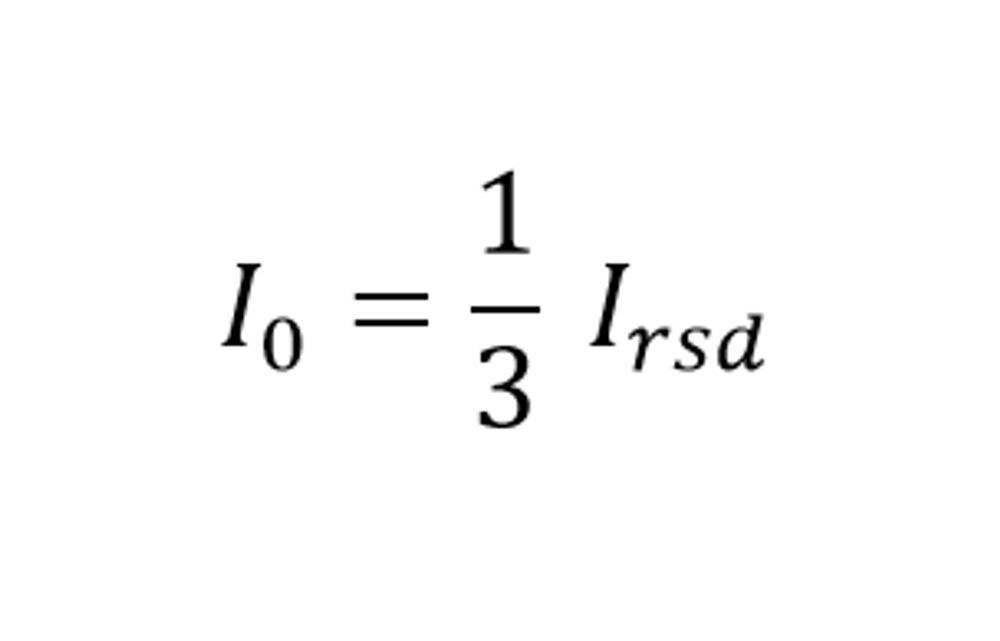
The zero sequence element appears when there is a connection of one of the phases to earth. This earth leakage, or energy lost out of the system, shows as an imbalance in the three phase currents. Zero sequence current and Residual/Neutral current are intimately related, by the following equation:

This relationship to leakage current explains why zero-sequence elements are used for earth faults. Older earth fault detection systems simply connected 3 CT’s in series across all phases. Under balanced conditions, Irsd (and therefore I0) would be zero. Under earth fault conditions, the balance would be lost with energy escaping to earth, resulting in a non-zero Irsd upon which the relay would trip.
Zero sequence components are often used for detecting the direction of Earth Faults, allowing protection engineers to distinguish between genuine downstream earth faults and sympathetic capacitive currents.
Which leaves us with the last element, Negative Sequence. To understand this element, it is best to think of the fault scenario which would be missed by the positive and zero sequence conditions. What if there was a phase discontinuity, for arguments sake a break in phase A?
Current would continue flowing in the remaining healthy phases B and C, but the current in Phase A would be zero. The increase in energy flowing through phases B and C may not be high enough to trigger an overcurrent operation, so positive sequence may miss the fault. Assuming that the broken cable is not touching the earth, there is no leakage current, suggesting that zero sequence/residual based current wouldn’t cause a protection actuation. How do we detect this scenario?
Negative Phase Sequence detects imbalances in the network that does not cause energy loss out of the system. For broken conductors, or for line to line faults, NPS provides sensitivity to fault scenarios that would be missed by overcurrent and earth fault. The imbalance between the phases causes NPS to be non-zero, and by setting a protection on the basis of NPS level, we can trip even if one of the phases is under current, not just overcurrent.
“NPS can be used to improve protection sensitivity by detecting scenarios often missed by conventional OC and Earth Fault relaying methods,” reports NOJA Power Group Managing Director Neil O’Sullivan. An extension of this function is the ANSI 46 BC broken conductor protection available in our reclosers, which combines our NPS detection with Positive Sequence Current to determine the I2/I1 ratio. This simplification allows for easy relay setting, as the operating quantity is set in percentage, rather than amperes making the function viable when NPS impedance parameters are not available to engineers.”
Negative Sequence Protection fills in the protection gap left by Overcurrent and Earth Fault protection, by catching the scenarios of broken conductors or ungrounded faults such as line to line faults. An added benefit is insensitivity to load – NPS does not care what the load current is, it is only acting on the imbalance between phases, giving greater specificity of protection, regardless of whether load is 10 amps or 10,000 amps.
NOJA Power’s OSM Recloser system provides Negative Phase Sequence Protection as standard, along with the more commonly used Overcurrent and Earth Fault protection. By incorporating NPS into network standard protection, engineers can be sure to improve network safety and reliability by improving fault detection selectivity and accuracy. With over 90,000 installations in 104 countries worldwide, NOJA Power can support you in deploying Negative Phase Sequence protection in your network to secure an improvement in safety and reliability.
Want to stay up to date with Electrical Distribution Technology?
Join our list for a free weekly technical bulletin, as we share our Global Electrical Engineering experience directly to your inbox.
Subscribe →